
Three verbs that do not mean the same
- View
- Recognize deformed shape, critical areas, signs and discontinuities.
- Extract
- Convert a specific result into a reproducible parameter.
- Validate
- Compare that parameter with independent evidence and a justified tolerance.
PLNSOL helps you interpret the result, but it does not generate quantitative evidence by itself.
*GET extracts a number, but does not validate it either. Validation requires a defined
reference, error measure, and decision rule.
Activate the correct state
/POST1
*GET,n_sets,ACTIVE,0,SET,NSET

*IF,n_sets,GE,1,THEN
  SET,LAST
  solution_available=1
*ENDIF

RSYS,0
SET,LAST loads the last stored result set. RSYS,0 expresses the
results in global Cartesian coordinates. This matters especially for
S,X: a component without a declared coordinate system is incompletely defined.
First inspection — The deformed shape
/GRAPHICS,POWER
PLDISP,2
Before looking at stresses, check that the deformation corresponds to the expected mechanism: zero displacement at the support, downward tip motion, and smooth curvature. An unexpected shape should be investigated before calculating error percentages.
The plot scale factor may exaggerate the deformation. Use the scaled shape to recognize the pattern, not to measure the deflection visually.
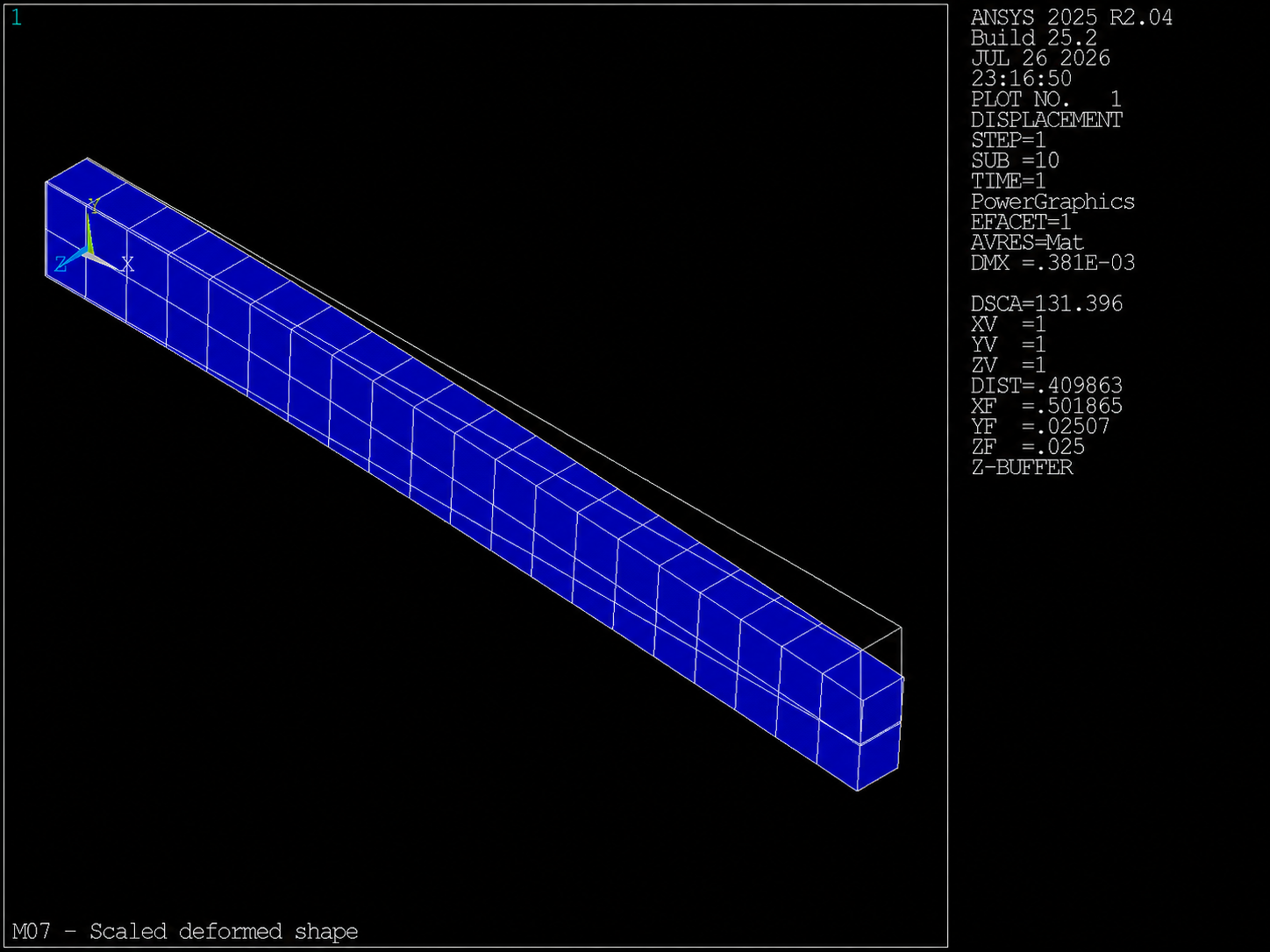
PLDISP,2). The exaggerated scale reveals the mechanism; it does not show the true displacement magnitude.
Why a node does not necessarily represent a section
M04 needed an identical probe between meshes and used the geometric node
(L,0,0). M07 asks a slightly different question: how far does the
entire end section move?
To answer we will use all the nodes of tip_nodes and we will keep the
M04 node as secondary control. This way we avoid turning a particular corner into a
property of the entire face.
Extract the average deflection
CMSEL,S,tip_nodes
node_id=0
uy_sum=0

*DO,j,1,n_tip
  node_id=NDNEXT(node_id)
  *GET,uy_node,NODE,node_id,U,Y
  uy_sum=uy_sum+uy_node
*ENDDO

uy_tip_avg=uy_sum/n_tip
The pattern is familiar: select → scan → read → accumulate. The difference is that
*GET now reads the result set rather than the geometry or loads.
Average and dispersion tell different stories
In addition to the average we keep:
uy_tip_min
uy_tip_max
uy_spread = uy_tip_max−uy_tip_min
uy_spread_ratio = |uy_spread|/|uy_tip_avg|
The average approximates the translation of the section. The spread indicates whether the face moves
almost like a rigid section or presents significant warping and local variations. M07
requires a dispersion less than 1 %.
Traceability with M04
NSEL,S,LOC,X,beam_l
NSEL,R,LOC,Y,0
NSEL,R,LOC,Z,0
*GET,corner_node,NODE,0,NUM,MIN
*GET,uy_tip_corner,NODE,corner_node,U,Y
The ID is discovered only after the physical location is defined. With
KEYOPT(2)=3, the value should reproduce
−3.79470E−4 m within 0.1 %. If it does not, M07 is not
analyzing the same validation model.
The reference is not the absolute truth
Euler–Bernoulli assumes, among other things:
- linear, homogeneous and isotropic material;
- small deformations;
- flat sections that stay flat;
- negligible shear deformation;
- idealized load and support.
The 3D solid is not identical to that one-dimensional model. A small error supports consistency between them, but even a perfect match would not prove that every assumption is correct.