
Your first check
Immediately after running, perform these four checks:
- The solver finished without a fatal error.
- The file
m00_cantilever.rstexists. - The free end moves toward −Y.
- Displacement is on the order of tenths of a millimetre, not metres or microns.
Displacement reference
For a rectangular beam with Euler–Bernoulli theory:
I = B·H³/12
|uy_tip| = P·L³/(3·E·I) ≈ 3.81E-4 m ≈ 0.381 mm
You do not need to memorize 0.381 mm. Use it as order-of-magnitude guidance.
The template runs PLNSOL,U,SUM in /POST1 right after
SOLVE; compare your prediction with the contour produced by the script.
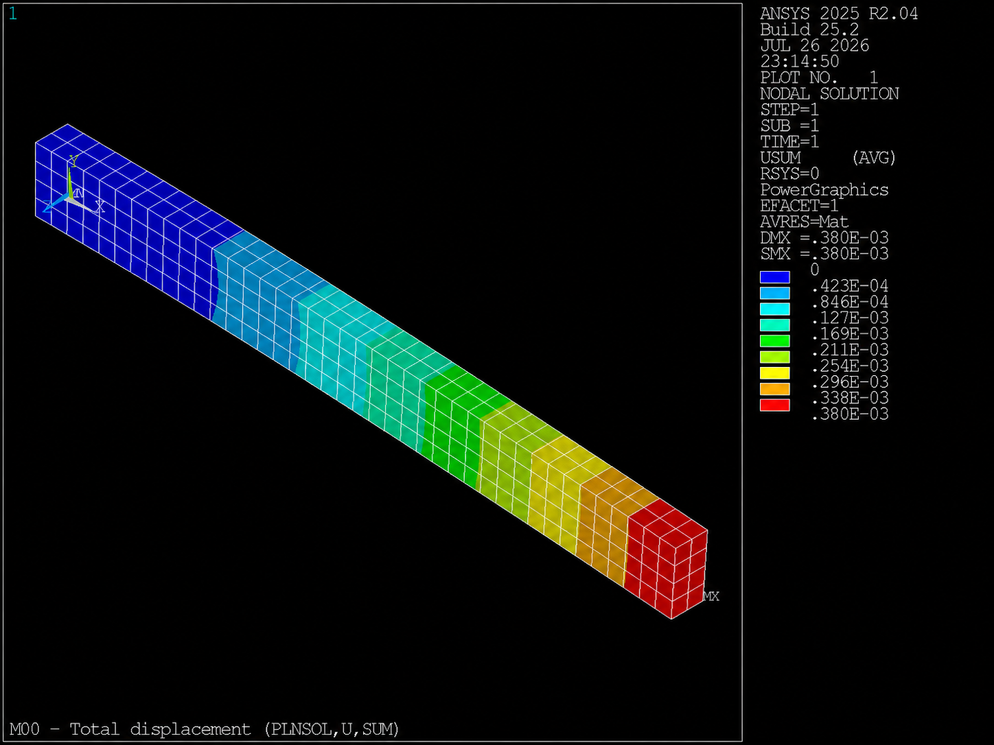
PLNSOL,U,SUM).
Compare −Y direction and order of magnitude with the analytical prediction.
Check your model: contrast prediction and contour; do not memorize the decimal. The 3D solid model does not have to match Euler–Bernoulli exactly; M04 and M07 will turn this comparison into a formal study.
Stress reference with Navier
Just as we predicted deflection, we can estimate bending stress with the
Navier flexure equation. At the fixed support (x = 0) bending moment is maximum:
M_max = P·L
σ_ref = M_max·y/I     with y = H/2
σ_ref ≈ 12 MPa
Substituting model values (P = 1000 N, L = 1 m,
H = 0.10 m, I = 4.1667E-6 m⁴) gives
σ_ref ≈ 12.0 MPa. Under dominant bending, the von Mises equivalent stress plotted by
PLNSOL,S,EQV should be compared by order of magnitude against
σ_ref. The peak usually appears near the fixed support, not at the loaded tip.
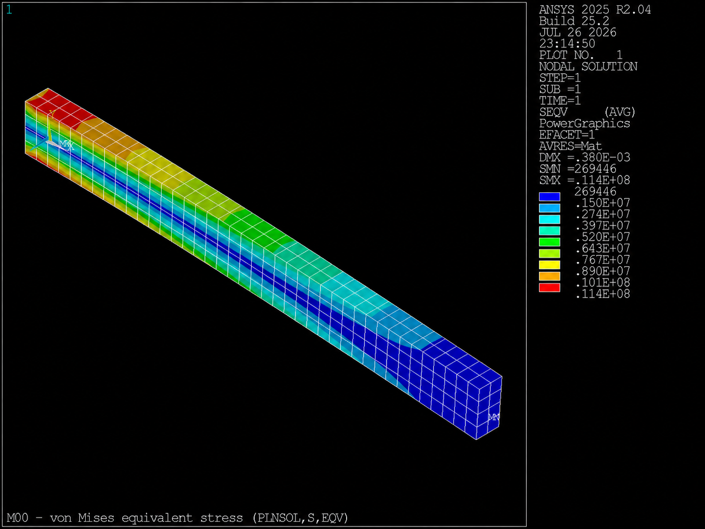
PLNSOL,S,EQV).
Compare peak order of magnitude with σ_ref.
Engineering insight: a meshed 3D solid does not reproduce the Navier–Euler beam exactly.
M01 will turn uy_ref and sigma_ref into verifiable parameters; M07 will formalize
the FE/analytical comparison.