
Skip to content
Marc & Structures
Index

Save your progress

Enter your email and we will send a secure sign-in link. There is no password and the first link creates your account.

Mental model ~5 min · ~69 min remaining

Head, thread, and connector

Two pilot nodes, absorbed regions, MPC184 vs. BEAM188, and an external code check.

Operational mental map

Idealised joint: kinematics, stiffness, and force

CERIG and the 1D connector represent different parts of the joint and require separate verification.

Complete the diagram from memory

Predict the missing relationships before revealing the model

Write the idea, not the exact wording. The comparison is feedback, not a grade.

3 missing links
1Input

Regions

Head and thread selected with controlled counts.

Mental model — Head, thread, and connector
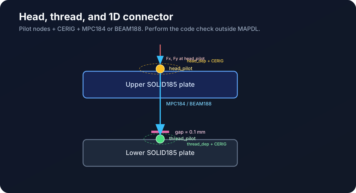
Two plates with CERIG pilot nodes and a 1D connector
Figure 1. Head on the upper face; thread on the lower interface; connector between pilots.
  • Head: head_pilot + head_dep at y=2·plate_t+gap.
  • Thread: thread_pilot + thread_dep at y=plate_t.
  • CERIG: use UXYZ for the dependent SOLID185 translations. Pilot rotations remain in the equations to transmit moments.
  • Standards: MAPDL provides forces; code-based sizing is performed externally.
Quick check

Why use CERIG,pilot,ALL,UXYZ with SOLID185 dependent nodes?