
M11 introduced 3D contact between meshed bodies. M12 opens the
third optional specialization: connecting two SOLID185
plates through pilot nodes, rigid regions with CERIG, and a comparable
1D connector (MPC184 or BEAM188). You will extract local forces
to CSV for checking the bolt outside MAPDL under the applicable standard.
Your mission
You will idealize the head and thread with two pilot nodes, compare a rigid connector with an elastic one, and document equilibrium and forces with reproducible CSV evidence.
Guiding question: can you prove that the load passes through the bolt rather than through a numerical bond between the plates?
Objectives
After completing M12, you will be able to:
- Select nodes captured by the head and thread using auditable components.
- Apply
CERIG,pilot,ALLto captured regions of three-dimensional solids. - Build
MPC184(Lagrange KEYOPT) andBEAM188(CSOLID) connectors. - Avoid accidental bonding with a documented
interface_gap. - Extract connector
SMISCresults and interpret the local 1D coordinate system. - Export forces to CSV for code verification outside the model.
Prerequisites and downloads
- M03:
BEAM188, sections, and beam degrees of freedom. - M06: global equilibrium and reaction summation.
- M02: selection with
NSEL,CM, andSELTOL. - M11 (recommended): gap criteria and diagnosis before trusting stresses.
12_start.mac— starting point.12_bolt_connector.mac— audited deliverable.12_bug_hunt.mac— five faults.12_challenge.mac— verifiable challenge.12_expected_results.csv— numerical contract.bolt-pilot-cerig.svg— head/thread diagram.mpc-vs-beam188.svg— connector comparison.
How to use this lesson
| Path | Duration | Coverage |
|---|---|---|
| First win | 20–25 min | Geometry, CERIG, MPC184, and the first force CSV. |
| Complete | 70–75 min | BEAM188, comparison, debugging, challenge, and mastery. |
Session map
- Mission: objectives, downloads, and prediction.
- Mental model: pilots, CERIG, connectors, and external standards.
- Demonstration: gap, selection, solution, and CSV.
- Debugging: five common faults.
- Challenge: stiffness or effective length.
- Mastery: final M12 test.
Prediction — What happens before SOLVE?
Two 80×40×12 mm plates with a 0.1 mm gap and Fx=4000 N, Fy=−3000 N applied at head_pilot.
| Quantity | Value | Interpretation |
|---|---|---|
| Interface gap | 0.0001 m | No shared nodes between plates |
| Captured head/thread nodes | 25 + 25 | Auditable selection with mesh_h=0.004 m |
| Topology | 1848 nodes / 1200 SOLID185 elements | Two blocks meshed separately |
| Load | head_pilot | Main load path through the 1D connector |
Prediction: if you omit the gap, the plates share nodes at y=plate_t and some of the load bypasses the bolt. With the gap, the local forces must balance the applied Fx and Fy.
Mental model — Head, thread, and connector
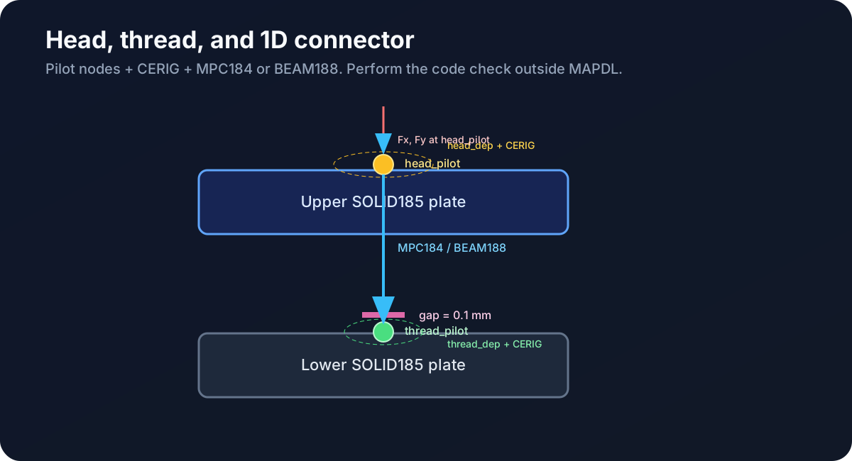
- Head:
head_pilot+head_depat y=2·plate_t+gap. - Thread:
thread_pilot+thread_depat y=plate_t. - CERIG: with
ALLonSOLID185, only active translations (UX,UY,UZ) are coupled. - Standards: MAPDL provides forces; code-based sizing is performed externally.
Step 1 — Geometry and mesh
BLOCK,0,plate_x,0,plate_t,0,plate_z
BLOCK,0,plate_x,plate_t+interface_gap,2*plate_t+interface_gap,0,plate_z
VMESH,ALL
Document interface_gap in the README and CSV. Confirm that there is no unintended continuity between the plates.
Step 2 — Captured regions and CERIG
NSEL,S,LOC,Y,2*plate_t+interface_gap
NSEL,R,LOC,X,bolt_x-head_absorb_r,bolt_x+head_absorb_r
NSEL,R,LOC,Z,bolt_z-head_absorb_r,bolt_z+head_absorb_r
CM,head_dep,NODE
*GET,head_pilot,NODE,0,NUM,MIN
CMSEL,S,head_dep
CERIG,head_pilot,ALL
Repeat at y=plate_t for the thread. With SOLID185, ALL is valid: MAPDL uses only the solid's active DOFs. Verify counts of 25+25 before creating the connector.
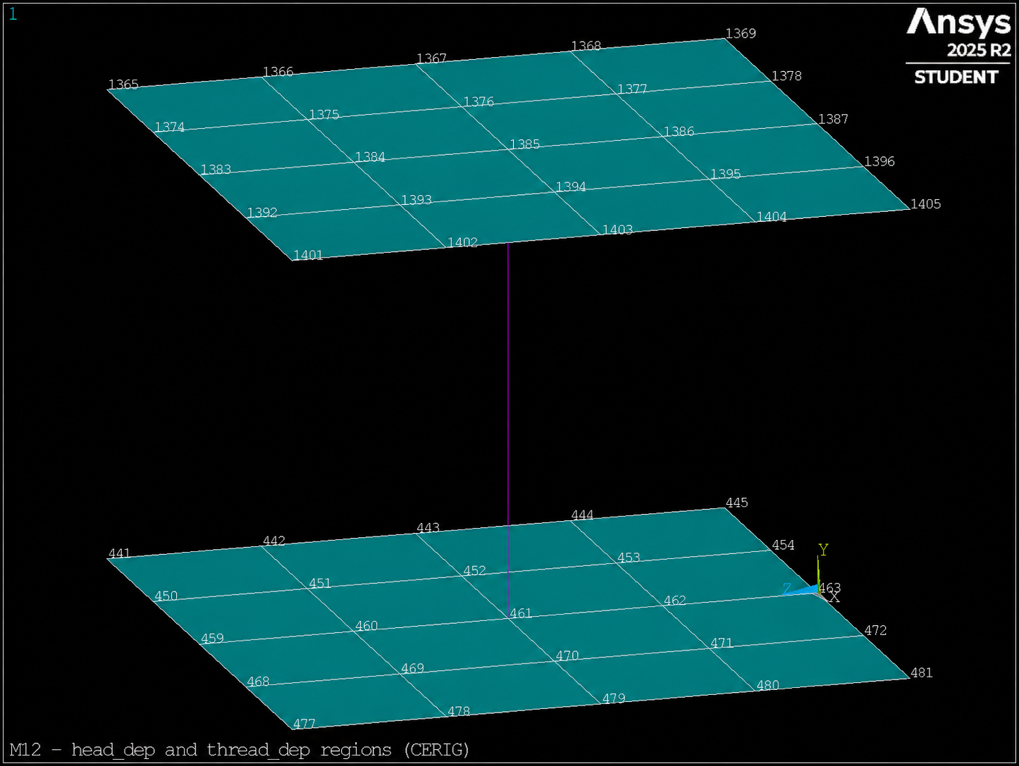
head_dep and thread_dep selection before CERIG and the 1D connector.Step 3 — MPC184 and BEAM188 connectors
ET,2,MPC184
KEYOPT,2,1,1
KEYOPT,2,2,1
E,head_pilot,thread_pilot

ET,2,BEAM188
SECTYPE,1,BEAM,CSOLID
SECDATA,bolt_d
E,head_pilot,thread_pilot
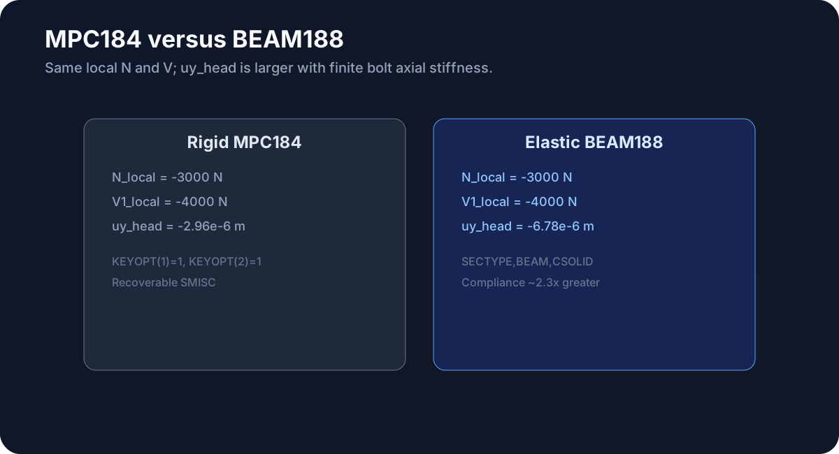
MPC184 case: rigid beam with Lagrange multipliers to recover SMISC. BEAM188 case: finite axial bolt stiffness. Load: F,head_pilot,FX and FY.
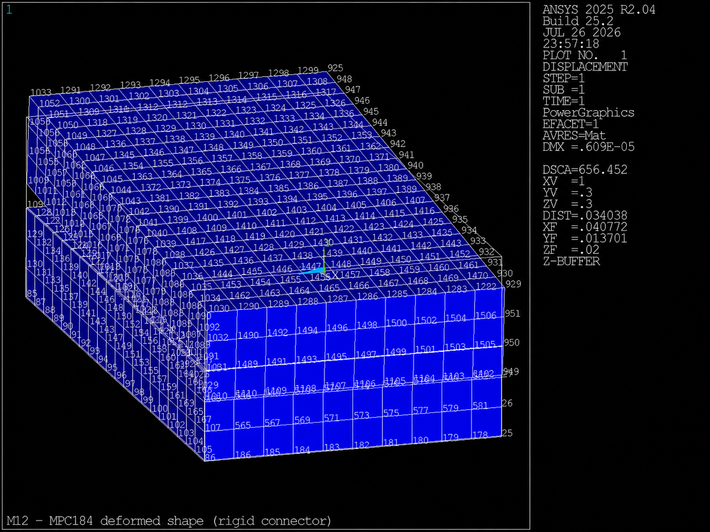
MPC184 (rigid connector).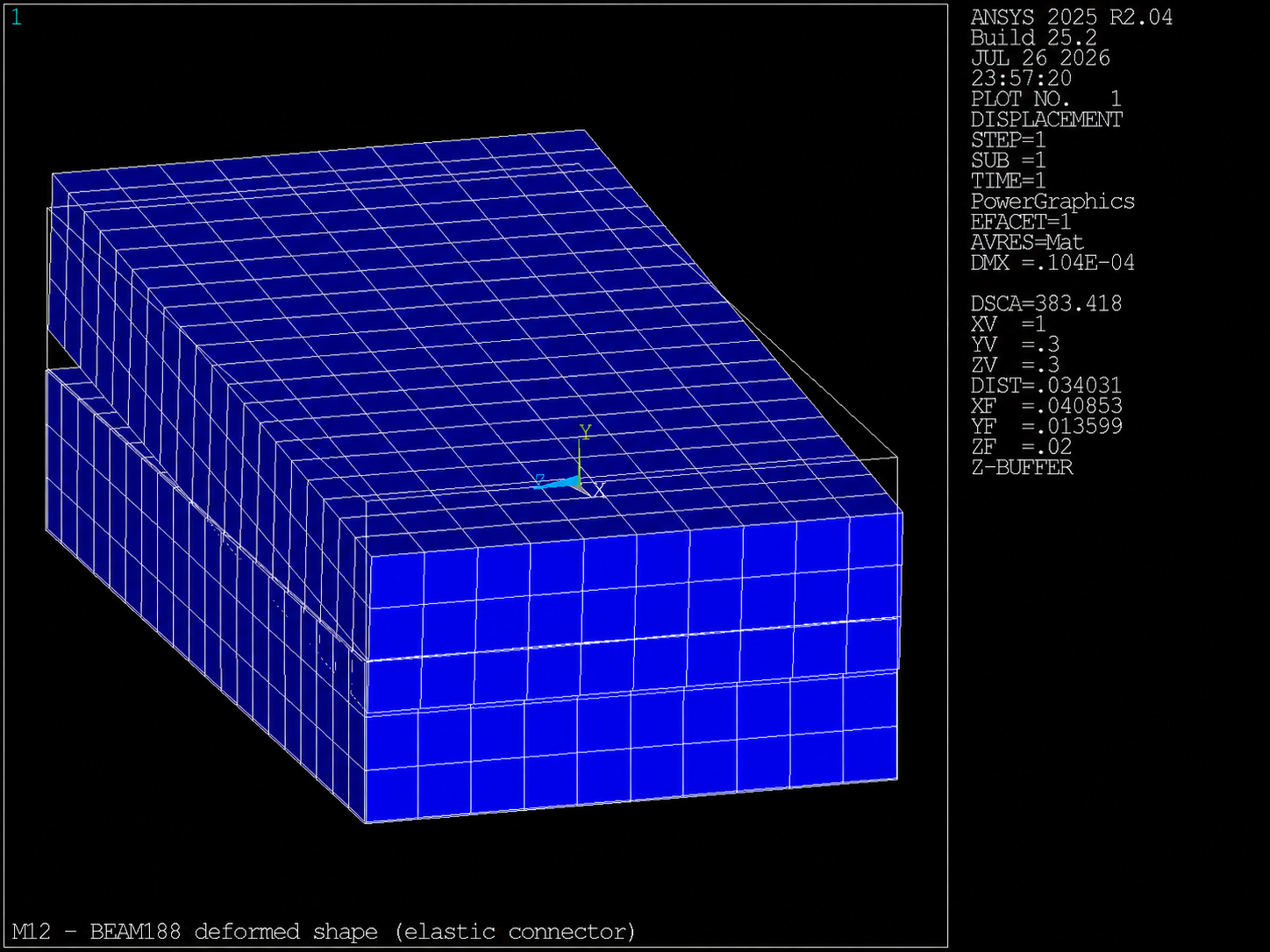
BEAM188: same load, greater head compliance.Step 4 — Postprocessing and CSV
ETABLE,N_local,SMISC,1
ETABLE,V1_local,SMISC,6
*GET,N_local,ELEM,conn_elem,ETAB,N_local
Write m12_bolt_forces.csv with forces in the connector's local coordinate system. Measured reference: N_local=−3000 N, V1_local=−4000 N; study_passes=1. The file includes the note export_for_external_code_check.
Bug hunt
Five scenarios documented in 12_bug_hunt.mac:
- Pilot incorrectly included only as a dependent node without a valid mesh.
- Pilot included in the
CERIGdependent set. MPC184with KEYOPT(2)=0 and empty SMISC output.BEAM188withoutSECTYPE,BEAM,CSOLID.- Trusting bolt forces without global support equilibrium.
Verifiable challenge — Stiffness or length
After validating the base deliverable, choose Challenge A (increase bolt_d) or Challenge B (increase plate_t and connector length). Predict the change in uy_head_beam before running.
Self-assessment
Quick questions
- Why is
interface_gapintroduced? - How does rigid MPC184 differ from BEAM188 in this lesson?
- Where is the bolt's code compliance check performed?
Learning evidence
m12_connector_audit.csv— two rows withpasses=1.m12_bolt_forces.csv— forces for external code checking.m12_summary.csv—study_passes=1.- Brief note explaining the connector's local versus global coordinate system.
Exit checklist
- 0.1 mm gap documented; no numerical bonding.
n_head_dep=n_thread_dep=25.CERIG,pilot,ALLat the head and thread (active solid DOFs).- MPC184 and BEAM188 with local N/V consistent with the load.
- Global equilibrium <0.5% in both cases.
study_passes=1in a clean run.
Technical traceability
Commands: CERIG, MPC184, BEAM188, SECTYPE, SECDATA, ETABLE, SMISC, *GET. Reference: Structural Analysis Guide; Element Reference. Inherited from: M03 (beam), M11 (gap). Next: M13 modal analysis.